FGMesh
User Manual & Technical Datasheet
FGMesh
User Manual & Technical Datasheet
Technical reference and user manual for wireless mesh network modules based on the ADF7023 transceiver and ESP32 / STM32 microcontrollers.
Table of Contents
1. Pin Maps & Hardware Configurations
The FGMesh wireless transceiver module is designed to operate on two distinct microcontroller architectures: ESP32 (highly versatile with WiFi/BLE support) and STM32 (ultra-low power and highly deterministic). Both configurations interface with the high-performance Analog Devices ADF7023 sub-GHz transceiver via a standard 4-wire SPI bus, utilizing an external interrupt line (IRQ) for packet-reception synchronization.
1.1 General Hardware Specifications
| Parameter | Specification Value | Notes |
|---|---|---|
| Operating Voltage | 3.3V DC (±5%) | Common supply voltage for the MCU and ADF7023 transceiver |
| RF Transceiver | Analog Devices ADF7023 | Sub-GHz FSK/GFSK transceiver |
| Frequency Range | 863.15 MHz – 869.95 MHz | Dynamic MAC-based sub-band allocation |
| Baudrate Interface | 1200 bps to 230400 bps | Configurable via UART AT commands (default: 115200) |
| Default Output Power | Up to +13.5 dBm | Software configurable via PL parameter |
1.2 STM32 Hardware Configuration
On the STM32 architecture (optimized for the STM32F4 series), the ADF7023 transceiver is mapped to the SPI1 port. The host interface utilizes USART1 for communication. Below is the pin mapping definition:
| Signal Name | STM32 Pin | Direction | Description |
|---|---|---|---|
| SPI SCK | PA5 | Output | SPI Clock to ADF7023 |
| SPI MISO | PA6 | Input | SPI Master In Slave Out from ADF7023 |
| SPI MOSI | PA7 | Output | SPI Master Out Slave In to ADF7023 |
| SPI CS | PA4 | Output | Active-low Chip Select line for ADF7023 |
| RF IRQ | PA8 | Input (Pull-down) | Hardware Interrupt from ADF7023 (Active High on packet sync/EOF) |
| LED Indicator | PB10 | Output | Activity LED indicating TX/RX packet processing |
| Host UART TX | PA9 | Output | Serial transmit output to Host controller (USART1) |
| Host UART RX | PA10 | Input | Serial receive input from Host controller (USART1) |
1.3 ESP32 Hardware Configuration
On the ESP32 platform, the module leverages standard GPIO mappings. Below is the pin mapping definition:
| Signal Name | ESP32 GPIO | Direction | Description |
|---|---|---|---|
| SPI SCK | GPIO 18 | Output | SPI Clock to ADF7023 (VSPI default) |
| SPI MISO | GPIO 19 | Input | SPI Master In Slave Out from ADF7023 (VSPI default) |
| SPI MOSI | GPIO 23 | Output | SPI Master Out Slave In to ADF7023 (VSPI default) |
| SPI CS | GPIO 5 | Output | Active-low Chip Select line for ADF7023 (VSPI default) |
| RF IRQ | GPIO 16 | Input | Hardware Interrupt from ADF7023 |
| LED Indicator | GPIO 2 | Output | Onboard status LED indicating TX/RX packet processing |
| Host UART TX | GPIO 1 (TX0) | Output | Serial transmit output to Host controller (UART0) |
| Host UART RX | GPIO 3 (RX0) | Input | Serial receive input from Host controller (UART0) |
| I2C SDA | GPIO 21 | I/O | SDA data line for SSD1306 OLED display (optional) |
| I2C SCL | GPIO 22 | Output | SCL clock line for SSD1306 OLED display (optional) |
2. Flashing & Programming Instructions
FGMesh provides pre-compiled firmware binaries for both microcontroller targets:
FGMesh_esp32.bin and FGMesh_stm32f4.bin. Follow the instructions below
to upload the appropriate binary to your module hardware.
2.1 ESP32 Firmware Flashing Guide
The ESP32 firmware is flashed using the standard command-line utility esptool.py.
Ensure Python is installed on your computer before proceeding.
- Check Python Installation: Open your terminal or command prompt and verify Python is available. If not installed, download it from Python's official website.
- Install esptool: Run the following pip command in your terminal to install
the esptool toolset:
pip install esptool - Identify COM Port: Connect the ESP32 module to your computer via USB
(utilizing the onboard USB-to-UART bridge) and identify the mapped COM port in Device
Manager (Windows) or via
ls /dev/tty*(Linux/macOS). - Erase Existing Flash: Erase the ESP32's non-volatile memory and settings
partition to prevent firmware conflicts (replace
COM3with your identified port):esptool --port COM3 erase_flash - Write Firmware Binary: Navigate to the directory containing the
FGMesh_esp32.binfile and execute the following command:esptool --chip esp32 --port COM3 --baud 115200 write_flash -z 0x0 FGMesh_esp32.bin
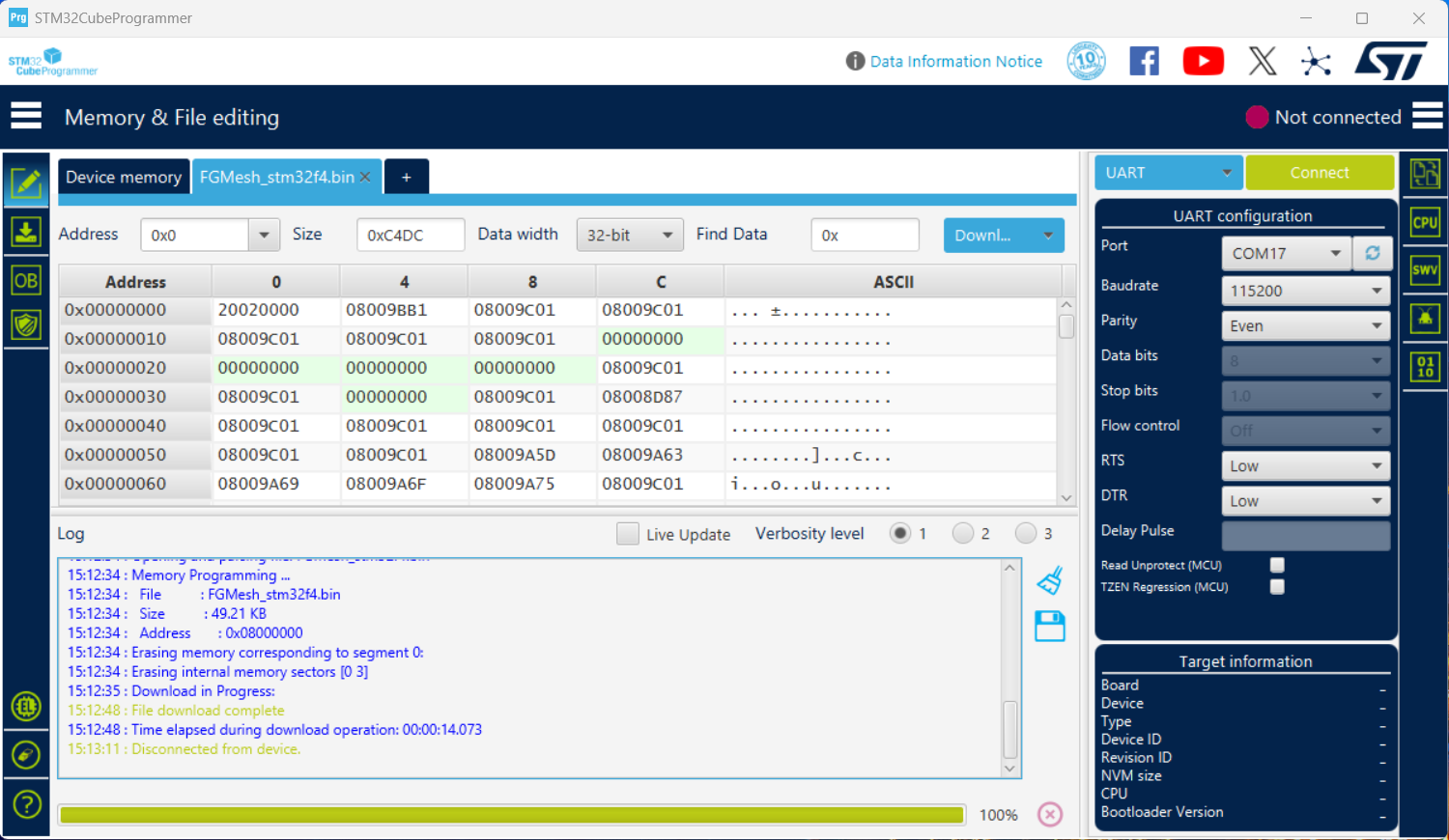
2.2 STM32 Firmware Flashing Guide
For the STM32F4-based FGMesh modules, programming is performed via a serial UART bootloader connection using the official STM32CubeProgrammer utility.
- Install STM32CubeProgrammer: Download and install the official tool from the STMicroelectronics website.
- Enable DFU / Serial Bootloader Mode:
- Set the
BOOT0hardware pin to HIGH (usually by placing a jumper on the BOOT header to connect BOOT0 to 3.3V). - Press the physical RESET button on the module (or cycle power) to force the STM32 to restart and boot into DFU/System Bootloader mode.
- Set the
- Configure STM32CubeProgrammer:
- Open the STM32CubeProgrammer application.
- Select UART as the connection type in the right sidebar.
- Select the correct COM port corresponding to your USB-to-UART interface connected to the STM32 PA9/PA10 pins.
- Click the Connect button.
- Upload Firmware:
- Once connected, click on the Open file tab and select
FGMesh_stm32f4.bin. - Click the Download button to write the binary to the STM32 memory.
- Once connected, click on the Open file tab and select
3. UART/API Protocol (XBee-style)
The FGMesh module interfaces with host systems using a serial UART protocol modeled after the industry-standard XBee API Mode 2 (escaped). This packet-oriented format ensures robust delivery, command execution, and status reporting over serial lines.
3.1 Serial Port Parameters
By default, the serial port is configured with the following parameters:
- Baud Rate: 115200 bps (configurable from 1200 bps to 230400 bps via the
BDcommand) - Data Bits: 8 (fixed)
- Parity: None (configurable via
NB, stored in NVS, but currently not implemented/applied to the UART driver) - Stop Bits: 1 (configurable via
SB, stored in NVS, but currently not implemented/applied to the UART driver)
NB) and stop bits (SB)
commands can be set and read back from RAM/EEPROM, they are not supported/not
implemented by the UART driver in the current firmware version and will not change
physical serial line settings.
3.2 API Frame Structure
Every UART packet is structured as a frame containing a start delimiter, length indicator, frame-specific payload, and a trailing checksum byte:
| Byte Index | Field Name | Value / Range | Description |
|---|---|---|---|
| 0 | Start Delimiter | 0x7E |
Indicates the beginning of an API frame. |
| 1 – 2 | Length | 0x0000 – 0xFFFF |
Number of bytes in the frame payload (excludes start delimiter, length, and checksum). Represented in Big Endian (MSB, LSB). |
| 3 | Frame Type | Variable | Identifies the API frame structure and purpose (e.g., TX request, AT command, status). |
| 4 – (N-1) | Frame Payload | Variable | Frame-specific data fields based on the Frame Type. |
| N | Checksum | 0x00 – 0xFF |
1-byte validation field to check transmission integrity. |
For example, when sending a frame to a destination node, index 5 of the payload corresponds to the LSB (lowest byte) of the MAC address, and index 12 corresponds to the MSB (highest byte). Similarly, the unique serial number commands
SH and SL return their
4-byte arrays in LSB-first order.
3.3 Checksum Calculation
The checksum is calculated by summing all bytes in the frame starting after the length
field (i.e., from the Frame Type byte up to the last payload byte), taking only the lowest 8
bits of the sum, and subtracting this value from 0xFF:
Checksum = 0xFF - (Sum of bytes from Frame Type to last Payload byte & 0xFF)To verify the checksum on reception, sum all bytes from the Frame Type through the Checksum byte.
The lowest 8 bits of the total must equal 0xFF.
3.4 Escape Control (API Mode 2)
To prevent control characters from appearing inside the frame payload and being misinterpreted by serial drivers, the protocol employs an escape character mechanism (API Mode 2):
- The escape control character is
0x7D. - When any of the following bytes occur in the frame payload, they must be escaped:
0x7E(Start Delimiter)0x7D(Escape Character)0x11(XON Flow Control)0x13(XOFF Flow Control)
- To escape a byte, insert `0x7D` before it and XOR the original byte with
0x20. E.g., a byte value of0x13is transmitted as the two-byte sequence0x7D 0x33.
3.5 Implemented Frame Types
0x08: AT Command Request
Used to query or configure local module parameters (e.g., reading MAC address, setting Baudrate).
| Field Offset | Size | Description |
|---|---|---|
| 3 (Frame Type) | 1 byte | Always 0x08 |
| 4 (Frame ID) | 1 byte | User-defined correlation value. A response frame will match this ID. Set to
0x00 to disable responses.
|
| 5 – 6 (AT Command) | 2 bytes | ASCII representation of the command (e.g., "NI" is
0x4E 0x49).
|
| 7+ (Parameter) | Variable | Optional parameter value. If omitted, the command acts as a query (Read). If present, it writes the parameter. |
0x88: AT Command Response
Sent by the module in response to an AT Command Request (0x08).
| Field Offset | Size | Description |
|---|---|---|
| 3 (Frame Type) | 1 byte | Always 0x88 |
| 4 (Frame ID) | 1 byte | Matches the Frame ID of the initiating request. |
| 5 – 6 (AT Command) | 2 bytes | ASCII command characters. |
| 7 (Status) | 1 byte |
0x00 = OK0x01 = Error0x02 = Invalid Command0x03 = Invalid Parameter
|
| 8+ (Data) | Variable | The query response value (if command was a read request). |
0x10: Transmit Request (ZB TX Request)
Used to send payload data to a specific node (Unicast) or to all nodes (Broadcast) in the mesh network.
| Field Offset | Size | Description |
|---|---|---|
| 3 (Frame Type) | 1 byte | Always 0x10 |
| 4 (Frame ID) | 1 byte | User-defined correlation value. A Transmit Status (0x8B) frame will match this ID.
Set to 0x00 to disable status frames. |
| 5 – 12 (64-bit Dest) | 8 bytes | 64-bit MAC address of destination node. Set to 0x000000000000FFFF for
Broadcast.
Firmware Address Parsing Note: Standard broadcast packets
utilize
0x000000000000FFFF. Due to Little-Endian parsing in the
firmware, this sequence is evaluated internally as
0xFFFF000000000000 (which is mapped to 0 within the
routing engine to denote a broadcast/mesh flood).
|
| 13 – 14 (16-bit Dest) | 2 bytes | Set to 0xFFFE (reserved for mesh compatibility). |
| 15 (Broadcast Radius) | 1 byte | Maximum number of hops (set to 0x00 for default). |
| 16 (Options) | 1 byte | Transmit options (set to 0x00). |
| 17+ (RF Data) | Variable | Data payload to transmit across the network. |
0x8B: Transmit Status
Reports the success or failure of a Transmit Request (0x10) routing operation.
| Field Offset | Size | Description |
|---|---|---|
| 3 (Frame Type) | 1 byte | Always 0x8B |
| 4 (Frame ID) | 1 byte | Matches the Frame ID of the initiating request. |
| 5 – 6 (16-bit Dest) | 2 bytes | Set to 0xFFFE. |
| 7 (Retry Count) | 1 byte | Number of RF retries performed. |
| 8 (Delivery Status) | 1 byte |
0x00 = Success (ACK received)0x25 = Route Not Found (routing table failure)
|
| 9 (Discovery Status) | 1 byte |
0x00 = No overhead0x02 = Route Discovery overhead occurred
|
0x90: Receive Packet (ZB RX Response)
Emitted by the module when data payload arrives from another node over the RF network.
| Field Offset | Size | Description |
|---|---|---|
| 3 (Frame Type) | 1 byte | Always 0x90 |
| 4 – 11 (64-bit Source) | 8 bytes | 64-bit MAC address of the sender node. |
| 12 – 13 (16-bit Source) | 2 bytes | Set to 0xFFFE. |
| 14 (Receive Options) | 1 byte |
0xC1 = Unicast packet0xC2 = Broadcast packet
|
| 15+ (RF Data) | Variable | Received data payload. |
3.6 Color-Coded Hex Examples
Example 1: Read Node Identifier (AT Command "NI" Request)
Request to read the current node name string parameter (unescaped length: 4 bytes):
7E 00 04 08 01 4E 49 5F
Detailed byte explanation:
7E: Start Delimiter00 04: Unescaped Length (4 bytes)08: Frame Type (AT Command Request)01: Frame ID (0x01)4E 49: AT Command "NI" (ASCII characters 'N' and 'I')5F: Checksum Calculation:0xFF - ((0x08 + 0x01 + 0x4E + 0x49) & 0xFF) = 0xFF - (0xA0) = 0x5F
Example 2: Unicast Transmit Request (Sending "HELLO" to Node)
Request to transmit data "HELLO" to target MAC 00 13 A2 00 41 C3 5A 4A (unescaped
length: 19 bytes):
7E 00 13 10 01 00 13 A2 00 41 C3 5A 4A FF FE 00 00 48 45 4C 4C 4F 20
7E: Start Delimiter00 13: Length (19 bytes payload)10: Frame Type (Transmit Request)01: Frame ID (0x01)00 13 A2 00 41 C3 5A 4A: 64-bit Destination AddressFF FE: 16-bit Address indicator00: Broadcast Radius (Default)00: Transmission Options48 45 4C 4C 4F: ASCII RF data payload "HELLO"20: Checksum byte
Example 3: Receive Packet (Escaped XOFF Character)
This received packet payload contains a MAC address 00 13 A2 00 41 AB F2 BE. The
second byte of the address is 0x13, which must be escaped on the serial bus:
7E 00 11 90 00 7D 33 A2 00 41 AB F2 BE FF FE C1 48 45 4C 4C 4F EB
00 11: Length field remains 17 bytes (the escaped sequence7D 33counts as 1 single byte0x13in length).7D 33: Escaped byte representing0x13(computed as0x33 ^ 0x20 = 0x13).
4. Supported AT Commands & Configuration Options
The FGMesh module supports a wide array of AT commands for reading hardware characteristics,
configuring parameters in Non-Volatile Storage (NVS), and executing diagnostic commands. In API
Mode, AT commands are queried or written using the 0x08 AT Command
Request frame, and responses are returned using the 0x88 AT
Command Response frame.
4.1 System & Memory Commands
These commands control module reset, NVS configuration storage, and default settings restoration.
| Command | Access | Parameter Range | Default | Status | Description |
|---|---|---|---|---|---|
| WR | W-Only | None | — | Implemented | Write: Commits all current configuration parameters to Non-Volatile Storage (EEPROM / NVS). Written values persist across power cycles. |
| AC | W-Only | None | — | Stub / Placeholder | Apply Changes: Evaluates and applies pending configuration changes instantly. Note: In the current firmware, changes are not dynamically applied to the active radio state. The command returns OK but does not trigger a physical reconfiguration. |
| RE | W-Only | None | — | Implemented | Restore Defaults: Resets all configuration settings to
factory-default values. A subsequent WR command is required to save
defaults to NVS. |
| FR | W-Only | None | — | Implemented | Software Reset: Restarts the system immediately. Performs a soft reboot of the ESP32 or STM32 MCU. |
4.2 Network & RF Parameter Commands
These commands manage the RF physical layer settings, destination hops, and MAC-level transmission behavior.
| Command | Access | Parameter Range | Default | Status | Description |
|---|---|---|---|---|---|
| ID | R/W | 0x0000 – 0xFFFF |
0x7FFF |
Stub / Placeholder | Network ID: Configures the logical network identifier. Note: Currently stored in NVS, but not active/utilized for logical packet filtering or network isolation in this firmware version. |
| HP | R/W | 0x00 – 0xFF |
0x00 |
Stub / Placeholder | Preamble ID: Sets the physical RF sync word prefix. Note: Stored in NVS, but not applied to configure the physical layer/registers of the ADF7023 transceiver. |
| PL | R/W | 0x00 – 0x0F |
0x04 |
Stub / Placeholder | TX Power Level: Stored output power index. Note: Stored in NVS, but does not configure the physical registers of the ADF7023 (always defaults to transceiver configuration defaults). |
| CM | R-Only | 4-byte Hex Array | 3E FF FD FF |
Read-Only Static | Channel Mask: Returns the physical channel mask of channels available for communication. Hardcoded return value, cannot be modified. |
| BH | R/W | 0x00 – 0xFF |
0x00 |
Stub / Placeholder | Broadcast Hops: Stored TTL/hop limit for broadcast packets. Note: Stored in NVS, but not processed or validated in the routing layer. |
| NH | R/W | 0x01 – 0xFF |
0x07 |
Implemented | Network Hops: Sets the maximum hop limit (TTL) for unicast AODV routing packets. Packets exceeding this limit are discarded. |
| NN | R/W | 0x00 – 0xFF |
0x03 |
Stub / Placeholder | Network Delay Slots: Configures slots for broadcast propagation spacing. Note: Stored in NVS, but currently not utilized in transmit/routing delays. |
| MR | R/W | 0x00 – 0xFF |
0x01 |
Implemented | Mesh Unicast Retries: Configures the maximum AODV routing retries for finding broken routes before declaring delivery failure. |
| RR | R/W | 0x00 – 0xFF |
0x0A |
Stub / Placeholder | Unicast MAC Retries: Stored link-level retries. Note: Stored in NVS, but not applied to the radio driver link-level retransmissions. |
| MT | R/W | 0x00 – 0xFF |
0x03 |
Stub / Placeholder | Broadcast Multi-Transmits: Stored duplicate transmit count for broadcast packets. Note: Stored in NVS, but not utilized by the transmission logic. |
4.3 Addressing, Discovery & Diagnostics
Commands relating to node identification, RF statistics, and remote network node mapping.
| Command | Access | Parameter Range | Default | Status | Description |
|---|---|---|---|---|---|
| SH | R-Only | 4-byte Hex Array | Hardware ID | Implemented (Swapped) | Serial Number High: Returns the lower 32 bits of the unique 64-bit MAC address of the microcontroller. Note: In this custom firmware, the outputs of SH and SL are swapped compared to standard XBee. SH returns the LSB (lower 32-bit half) in Little-Endian. |
| SL | R-Only | 4-byte Hex Array | Hardware ID | Implemented (Swapped) | Serial Number Low: Returns the upper 32 bits of the unique 64-bit MAC address of the microcontroller. Note: In this custom firmware, the outputs of SH and SL are swapped compared to standard XBee. SL returns the MSB (upper 32-bit half) in Little-Endian. |
| DH | R-Only | 4-byte Hex Array | 00 00 00 00 |
Stub / Placeholder | Destination Address High: Returns the upper 32 bits of target MAC address. Hardcoded to zero. Cannot be changed, as only API mode is supported. |
| DL | R-Only | 4-byte Hex Array | 00 00 FF FF |
Stub / Placeholder | Destination Address Low: Returns the lower 32 bits of target MAC address. Defaults to broadcast address. Cannot be changed, as only API mode is supported. |
| NI | R/W | ASCII String | " " (space) |
Implemented | Node Identifier: Sets or queries the human-readable string name of the node (up to 20 characters). Used in network node discoveries (ND). |
| NT | R/W | 0x0001 – 0xFFFF |
0x0082 |
Stub / Placeholder | Node Discover Timeout: Stored timeout for network discoveries. Note: Stored in NVS, but currently not active or enforced by the routing scan. Default is 0x0082 (130 deciseconds / 13 seconds). |
| ND | W-Only | None | — | Implemented | Network Discover: Triggers a background scan of all active FGMesh nodes in the area. Returns response frames matching discovered nodes' MAC addresses and names. |
| FN | W-Only | None | — | Implemented | Find Neighbors: Initiates a 1-hop neighbor scan to mapping direct RF nodes in range. |
| DB | R-Only | 0x00 – 0xFF |
— | Implemented | RSSI Readback: Returns the absolute RSSI value (in dBm) of the last successfully received RF packet. |
4.4 Serial Interfacing Commands
These commands manage the physical serial interface configuration connecting the module to the host.
| Command | Access | Parameter Range | Default | Status | Description |
|---|---|---|---|---|---|
| BD | R/W | 0x00 – 0x08 |
0x07 |
Implemented |
Interface Data Rate: Sets the UART baudrate index. Values map as
follows:0=1200, 1=2400, 2=4800, 3=9600,
4=19200, 5=38400, 6=57600,
7=115200, 8=230400.
Writing a new baudrate index instantly commits the value, saves settings, and
triggers a system reset to apply the new baudrate to the physical port.
|
| NB | R/W | 0x00 – 0x02 |
0x00 |
Stub / Placeholder |
UART Parity: Sets serial parity bit:0 = No Parity, 1 = Even Parity, 2 = Odd
Parity.Note: Stored in NVS, but currently not implemented in the UART serial driver (fixed at No Parity). |
| SB | R/W | 0x00 – 0x01 |
0x00 |
Stub / Placeholder |
UART Stop Bits: Sets serial stop bits:0 = 1 Stop Bit, 1 = 2 Stop Bits.Note: Stored in NVS, but currently not implemented in the UART serial driver (fixed at 1 Stop Bit). |
| AP | R-Only | 0x02 |
0x02 |
Read-Only Static | API Mode: Fixed at 0x02 representing XBee API Mode
with escape characters. |
4.5 Info & Version Commands
| Command | Access | Return Size | Value | Status | Description |
|---|---|---|---|---|---|
| VR | R-Only | 2 bytes | A0 07 |
Read-Only Static | Firmware Version: Reports firmware revision version. |
| HV | R-Only | 2 bytes | 45 44 |
Read-Only Static | Hardware Version: Reports hardware revision version (ASCII characters 'E' and 'D'). |
| VL | R-Only | 22 bytes | String | Read-Only Static | Version Long: Returns corporate developer info:
"factorial-group.com.ua".
|
| DD | R-Only | 4 bytes | 00 11 00 00 |
Read-Only Static | Device Type Identifier: Returns XBee-compatible device type descriptor code. |
5. Digi XCTU Compatibility & Limitations
The FGMesh firmware implements standard XBee API Mode 2 frames and AT command structures, making the module fully compatible with the official Digi XCTU configuration and diagnostic utility. This allows developers to use a visual interface to manage network parameters, test link quality, and execute discovery scans.
5.1 Adding the FGMesh Module to XCTU
Follow these steps to connect your FGMesh transceiver module to XCTU:
- Connect the FGMesh module to your computer's USB port via a USB-to-UART bridge.
- Open the Digi XCTU utility and click the Add Radio Module button (the icon displaying a radio module with a plus sign at the top-left of the window).
- In the configuration dialog (illustrated in the screenshot below), select the correct COM port corresponding to your connected USB-to-UART interface.
- Set the baud rate parameter to match the module configuration (default:
115200bps). Keep the remaining port settings at their default values (8 data bits, no parity, 1 stop bit).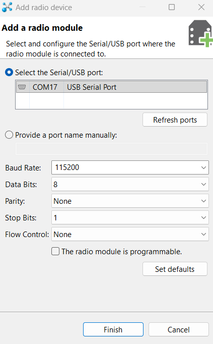
Figure 2: XCTU Add Radio Module Connection Settings - Click Finish to perform the device discovery.
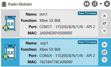
5.2 Connection Troubleshooting & Reboot Requirement
If the XCTU utility fails to communicate with the module, a retry dialog will appear containing troubleshooting instructions. For ESP32-based FGMesh modules, a hardware reset is required during this handshake:
- When prompted by XCTU to reset the radio module, press the physical RESET button on the ESP32 board.
- This reboots the MCU, allowing XCTU to synchronize and read the initial AT configuration parameters.
Once successfully discovered, the module will appear in the radio modules list on the left side of the window (as illustrated in the screenshot below):
5.3 Functional Limitations in XCTU
Since the FGMesh firmware is a custom implementation running on non-Digi hardware, there are several limitations to keep in mind when using XCTU:
- Firmware Updates: The "Update Firmware" button in XCTU is not supported. Any attempt to write a Digi binary over the FGMesh will fail. To update or flash FGMesh firmware, follow the instructions in Section 2.
- Transparent Mode (AT Mode): Only API Mode 2 with escape characters
(
AP = 2) is supported. The module cannot be configured in transparent character mode (command mode triggered via+++is inactive). - Simulated I/O Pins: Many hardware settings tabs in XCTU (such as digital output configuration, ADCs, and PWMs) display read-only default values. Changing these parameters does not toggle the physical pins of the ESP32 or STM32 MCUs.
6. Mesh Networking Behavior
FGMesh utilizes a custom wireless mesh networking architecture tailored for deterministic, low-latency, and multi-hop industrial communication. The system pairs the physical layer capabilities of the Analog Devices ADF7023 radio with a customized Ad-hoc On-Demand Distance Vector (AODV) routing protocol and a unique MAC-based channel swapping mechanism.
6.1 AODV Routing Protocol
Routes between nodes are established dynamically on-demand, minimizing background RF traffic. The routing algorithm relies on two primary control packets:
- Route Request (RREQ): Broadcasted by a node when it needs to find a path to a destination. The RREQ propagates through the network, building reverse path entries in the routing tables of intermediary nodes.
- Route Reply (RREP): Sent as a unicast back to the source once the destination (or a node with a fresh path to the destination) receives the RREQ. This establishes the forward path for data.
Key routing parameters and behaviors include:
- Path Selection: Based on the shortest path (minimum hop count) and link
quality. Packets received with an RSSI below
-90 dBmare ignored during route discovery to ensure only stable, high-quality links are chosen. - Route Lifetime: Active routes are stored in the local routing table with a
lifetime of 60 seconds (
ROUTE_LIFETIME_MS = 60000). If no data packets use a route within this window, it is purged. - Network Diameter: The maximum depth of the mesh network is capped at
4 hops (
MAX_HOPS = 4) to ensure low latency and packet delivery. - Broadcast MAC Address: The logical destination MAC address used to specify
broadcast frames is
000000000000ffff(represented in API frames as Big-Endian00 00 00 00 00 00 FF FF, which parses internally as0xFFFF000000000000/0due to the parser's Little-Endian byte-order logic).
6.2 Dynamic Channel Selection (MAC-based Frequencies)
To reduce collisions and mutual interference in dense environments, FGMesh implements a dynamic,
hardware-linked channel allocation. Instead of all nodes sharing a single channel, each node
operates on three unique, MAC-derived frequencies chosen from a 25-channel
master table (spanning 863.15 MHz to 869.95 MHz).
When a node boots up, it calculates its three dedicated frequencies using its hardware MAC address:
- Channel 0: Selected via
MAC_ID % 25 - Channel 1: Selected via
(MAC_ID * 3) % 25(frequency separation must be greater than400 kHzfrom Channel 0) - Channel 2: Selected via
(MAC_ID * 7) % 25(frequency separation must be greater than400 kHzfrom Channels 0 & 1)
6.3 Channel Swapping and Scanning (RX/TX)
Receiver Scanning (Idle RX Mode)
When a node is in an idle state waiting for packets, it continuously cycles through 5
channels every 1.5 milliseconds
(FREQ_SWAP_DELAY = 1500 microseconds):
- Its three unique MAC-derived Unicast channels (Channels 0, 1, and 2).
- The dedicated Broadcast RREQ frequency (
FREQ_BROADCAST_RREQ = 863.95 MHz). - The dedicated Route Reply frequency (
FREQ_RREP = 868.95 MHz).
Unicast Packet Transmission (TX)
When Node A wants to send a unicast packet to Node B:
- Node A calculates Node B's three unique working frequencies using Node B's MAC address.
- Node A transmits the payload sequentially across Node B's three channels. This multi-channel transmission ensures that even if one channel is affected by localized interference, the packet is successfully received on the others.
Broadcast Packet Transmission (TX)
Broadcast frames (such as routing RREQs or broadcast data payloads) are transmitted sequentially
on the global broadcast frequencies
(863.95 MHz and 868.95 MHz) to ensure all nodes in range receive them
regardless of their MAC-derived channel configurations. To execute a network-wide broadcast, the
API frame sent from the host must target the destination MAC address
000000000000ffff.
6.4 Collision Avoidance (CSMA/CA)
Before transmitting a packet on any frequency, the module performs a Clear Channel Assessment (CCA):
- The ADF7023 transceiver switches to the target channel in
PHY_RXstate and reads the RSSI value. - If the RSSI is greater than
-90 dBm, the channel is considered occupied. - The module waits for a randomized delay between 300 and 900 microseconds before retrying.
- The module will perform up to 100 CCA retries. If the channel becomes clear, the packet is transmitted. If the channel remains busy after 100 attempts, the transmission is aborted to avoid locking up the MCU.